Output Devices: OLED
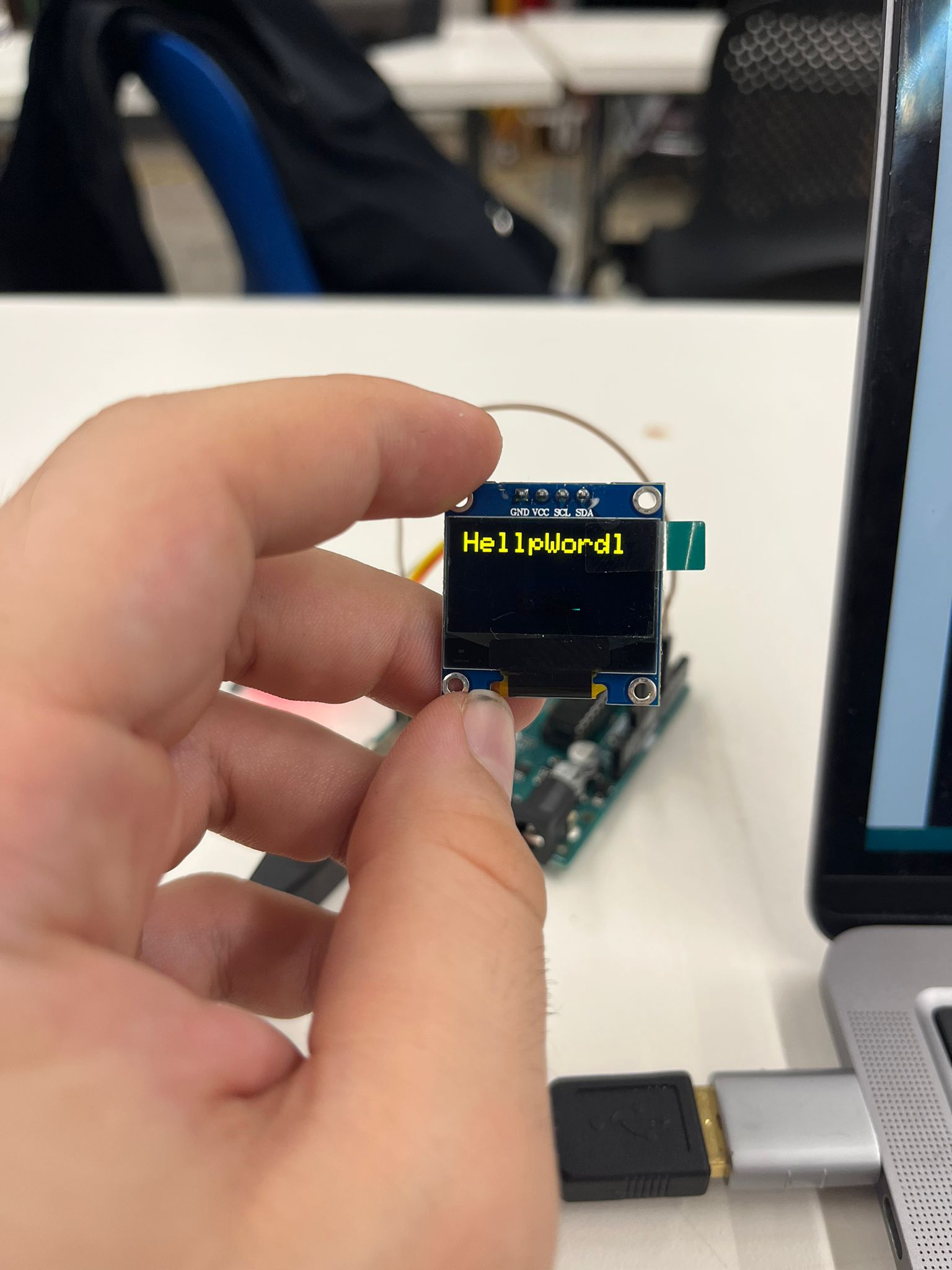
The OLED component when I was looking at it for the first time seemed pretty simple. It had four pins: VCC, Ground, SCL, and SDA. I had never seen SCL or SDA before so I went online to find out what they meant. SCL means serial clock and it carries the clock signal. SDA means serial data and it is the place of data transfer. These are all part of something called I2C (I^2C or Inter-Integrated Circuit) Protocol.
I2C
I2C protocol is meant to allow many IC's(Integrated Circuits) to communicate with one another through one or many controller chips. Other protocols are serial UART Ports, and SPI(Serial Peripheral Interface). The drawbacks are in serial UART Ports they use asychronous serial ports, meaning the clocks are not synced up, and if the data transfer rates are messed up the data will get messed up. UART ports use hardware to combining with software makes it hard. It only allows for communication with two devices. Lastly data rate is an issue. For SPI the most straightforward drawback is the number of pins required. SPI itself requires 4 pins and each peripheral device requires an extra I/O pin. But I2C is the best of both worlds. Only takes 2 wires and can connect up to 1008 devices. It also allows for a multicontroller system.OLED Work
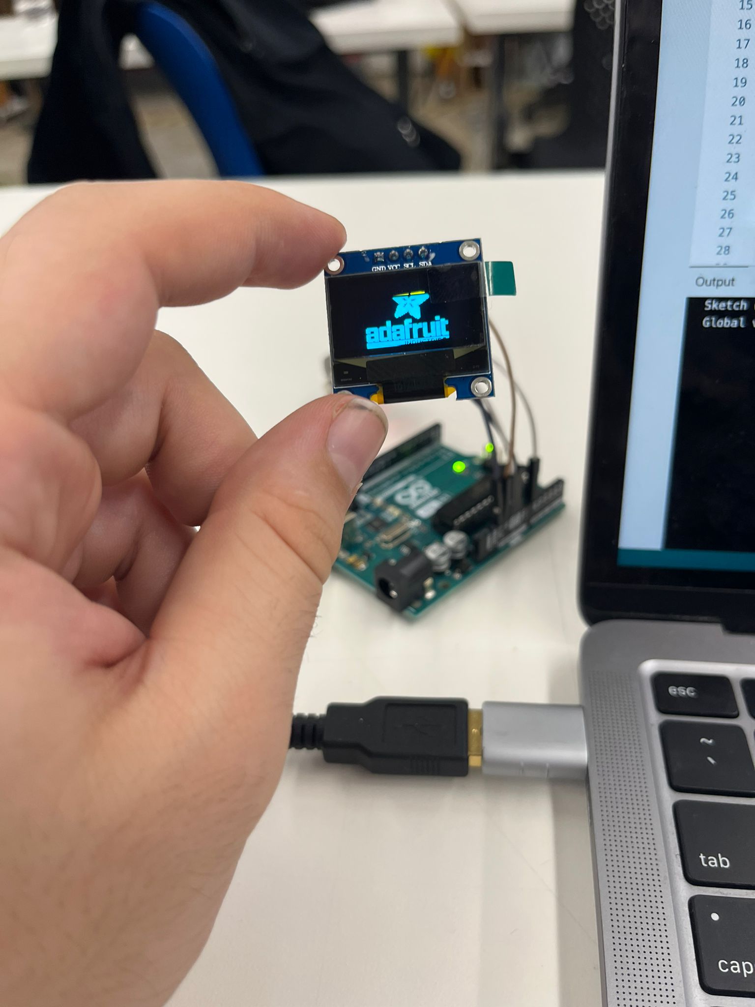
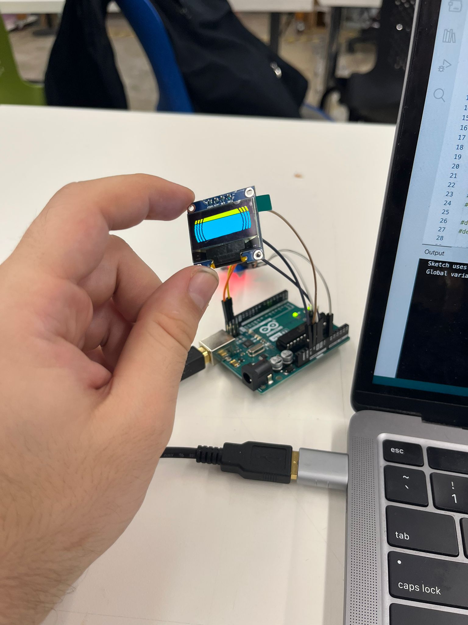
I started using an arduino because my D21E18A devkit has not become fully funcitoning yet. I will get to that later. Actually getting the OLED working was not that hard. Guide- I started by plugging in my VCC and Ground
- Plugging in the SCL and SDA pins
- Open Arduino
- Go to Manage Libraries
- Download Adafruit SSD1306
- Download Adafruit GFX
- Download I2C Scanner Script to find which port you are going to use
- There are example code that comes with SSD1306, for our speaker use as screen address 0x3C 128x32
- clearDisplay()
- display()
- setCursor(x,y)
- setTextColor(SSD1306_White)
- print()
Combining with a single gas sensor
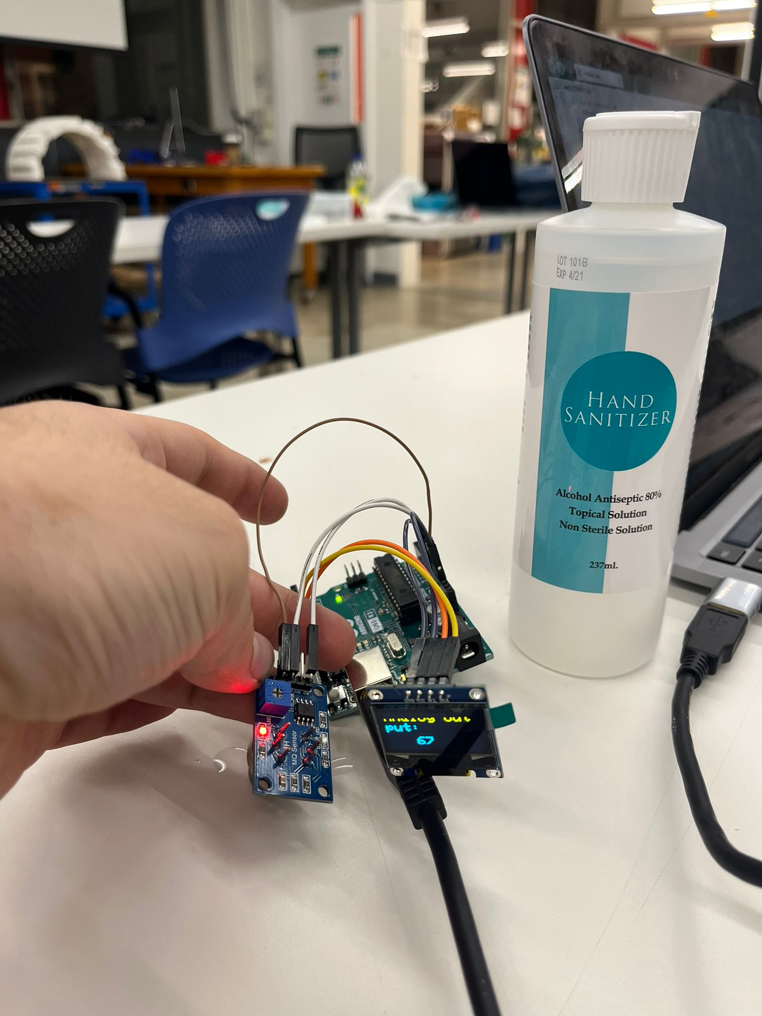
I used the work that I did last week, to get the analog output of the gas sensor to display on the OLED. Because I was using an arduino, I plugged in the gas sensor pins into the arduino. Then using software I took the number that the gas sensor was outputting and displayed it on the OLED.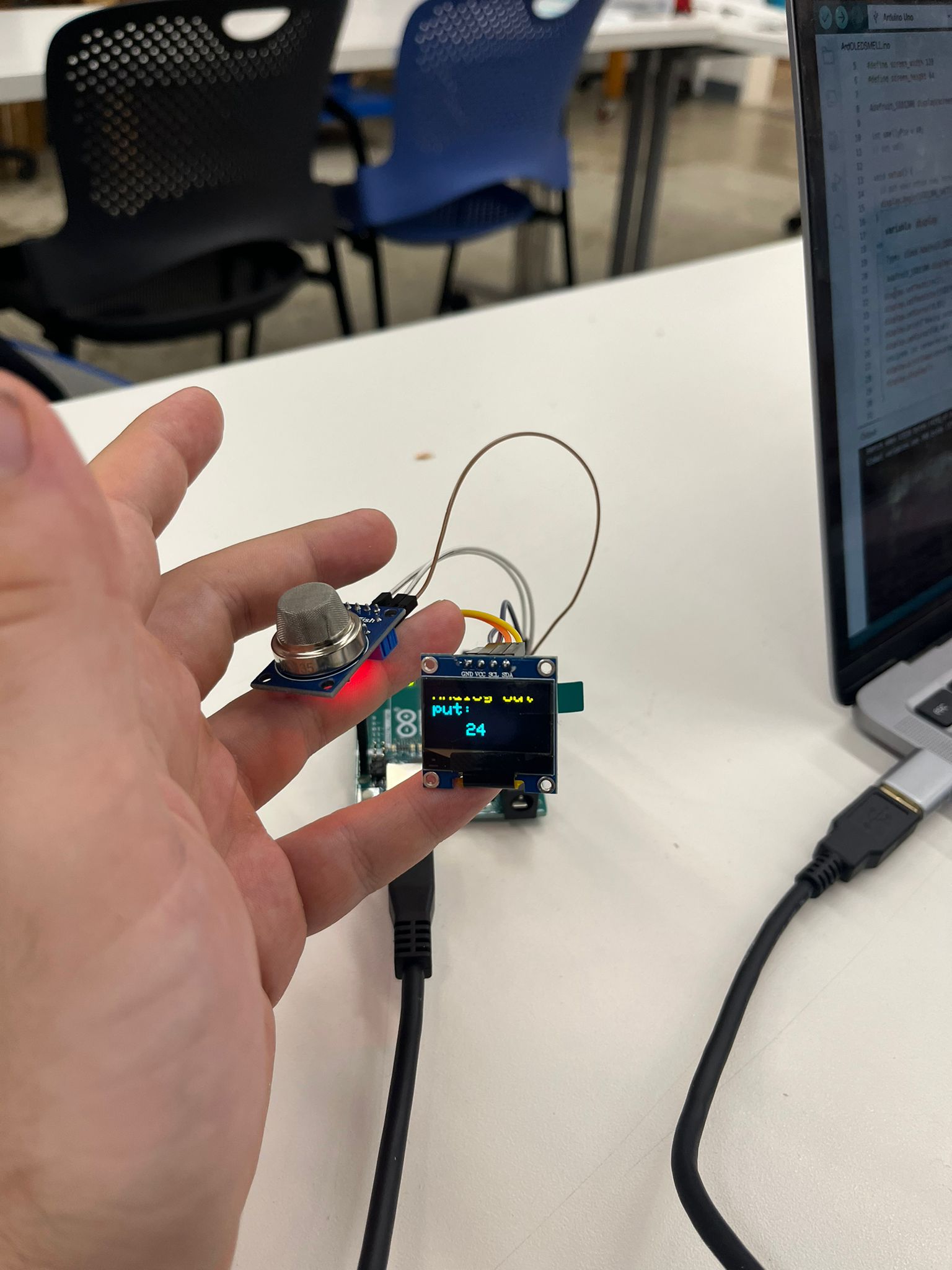
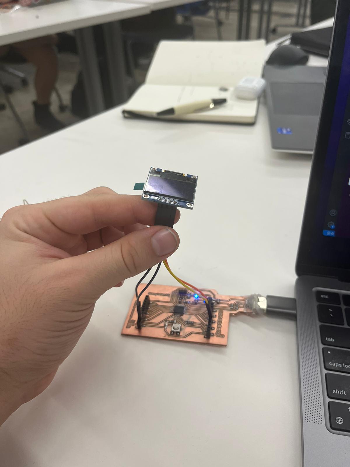
DevKit Work
I have been continuing to work on my devkit such that I can replace the arduino I am using with my OLED this week. Last week I had essentially copied Quentin's design. This week I tried to make it more my own. I still used the electronics principles but I added a button, and an 5V output. I have made some mistakes with soldering, which destroyed one of my boards. Another one of my boards was not programming because at first my soldering was not on the pads then when I went to fix it I made it worse and was not able to fix it.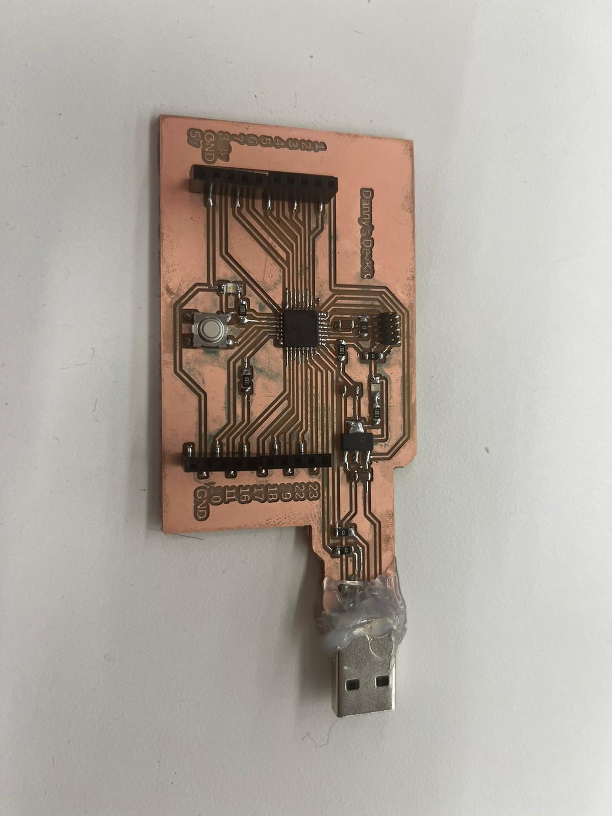
Some important resources I used this week:
-
OLED
oled -> Resources page -
Stepper Motor
stepper motor -> Resource Page -
Benjamin Cabe
His website -> Resource Page
Github Project -> Github
More in depth tutorial for Edge Impulse -> Tutorial -
Raeda- Noah Duetch
Raeda -> Site